How does the history of prosthetic development foreshadow the next breakthroughs in the field? What innovations can be made to modern prosthetics and how could these improvements be made to be the most impactful for people in their day-to-day lives? Can the design process consider a modular, task-based solution?
These are some of the questions I considered in my independent study on modern prosthetics this past Fall semester. Through field interviews with industry leaders, research in medical and engineering publications, and an iterative design process, I hoped to develop new approaches to the design of prosthetics.
I was fortunate to interview Alexander Thesleff, a Ph.D. student working with Dr. Ortiz-Catalan on transfemoral implementation of the OHMG. In addition to useful insight on the latest developments with osseointegrated solutions, Thesleff shared that lower limb prosthetics are lagging far behind upper limbs in terms of both research and application. This was the inspiration for my change in focus from hand prosthetics to a modular, activity-based, lower limb design.
In leg prosthetics, the knee joint is key to enabling an amputee’s mobility and strength. If successfully designed, it can allow for a full range of movement similar to that of a human limb. The joint system that I designed consists of three main parts: The Osseointegrated Implant Rod connects directly to the prosthetic knee joint. The data travels through wires in the center of the rod into the joint, where it is processed and turned into transferable signals. These signals then tell the joint how to move. The Processor Cylinder is where the sphere is housed. It contains the circuit boards that work with the OHMG to process the signals from the nerves and holds the motors that rotate the sphere. The Rotational Sphere is the knee joint itself. With a 3” diameter, it’s the component that connects to the lower leg and allows the limb to rotate in multiple ways.
This joint design is capable of simulating the exact movements of a human leg. It can rotate along the y-axis to an angle slightly larger than 90º, just as a knee would. It can also rotate along the x-axis. This is not normal movement for a knee, as horizontal rotation mainly comes from the hip. However, movement in the lower leg is instrumental in making this rotation–it generates momentum, stability, and strength. So, in order to simulate this movement, I decided to enable my joint design to rotate along the x-axis.
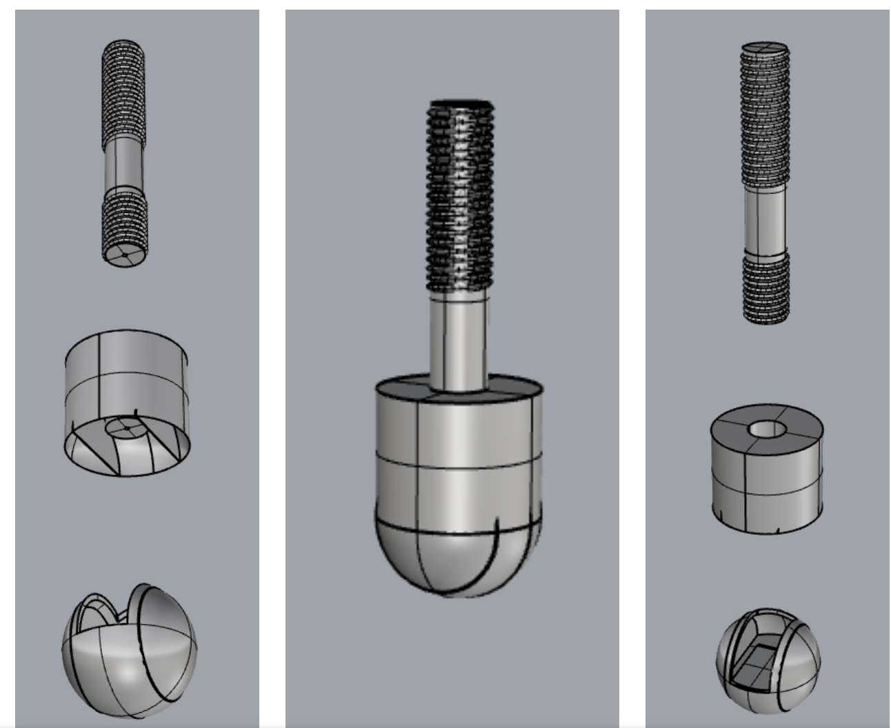
Top: Implant Rod; Center: Processor Cylinder; Bottom: Rotational Sphere
I wanted to focus my design on interchangeability. Prosthetic limbs are extremely expensive, especially when they are be controlled by the user's brain. Limbs with different functions are made as entirely separate limbs, with each component redesigned and rebuilt. Purchasing each one for different uses can be even more expensive, so I wanted to include an modular feature to minimize that cost.
Knee Interchangeability: at left, "Running Leg"; at right, "Ambulatory Leg"
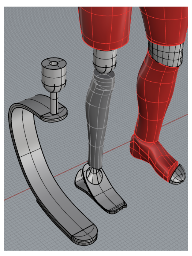
Foot Interchangeability: at right, "Everyday Foot"; at left, "Precision-Control Foot"
The Precision-Control Foot is designed for task-specific movements, such as driving or playing the drums, where control of ankle rotation is crucial. The Everyday Foot is created for low-impact activities, such as walking or light jogging, where the general motion of the entire leg is most valuable.
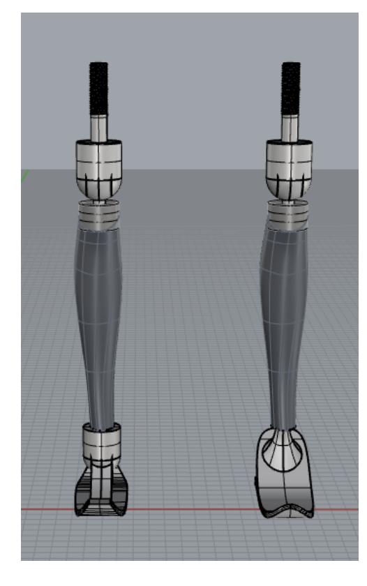
Left: Back View;
Right: Front View
Right: Front View
My design for the ambulatory leg is intended for low to medium levels of activity with minimal amounts of stress placed on the leg itself. Each leg is tailor-made for the user, based on a rendered 3D model of their opposite leg. The prosthetic is made with a 1/4" titanium 3D printed shell to maximize strength while minimizing weight. The leg has a connecting rod attached to the knee joint to provide full mobility.
My ambulatory foot design (below left) is specified for walking and general everyday activity. It is constructed of two sheets of 1/4" carbon fiber, shaped to absorb any stress that may be placed upon the leg or joints. The toe and heel also bend upwards so any obstructions on the ground won't cause the user to trip. The rod that connects the foot to the leg is encased in formed stainless steel. The support towards the back of the foot provides stability and allows the bottom carbon fiber sheet to bend, in turn providing more load absorption.
My precision-control foot design (below right) is focused on activities that place very little stress on the leg. Its main purpose is for uses that require control of the ankle and the foot. It is also made of a 1/4" carbon fiber sheet with stainless steel supports to connect to the ankle joint. The data processed by the circuit boards in the knee joint is sent through wires encased in rubber tubing in the leg. Once the signals reach the ankle joint, they tell it how to move. Just like the knee joint, it moves both on the x-axis and the y-axis. However, it has far less movement range than the knee joint, just as a real ankle would have.
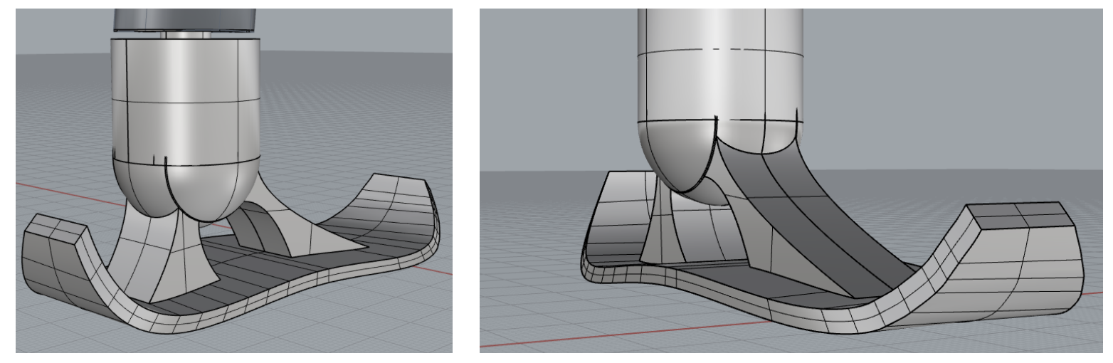
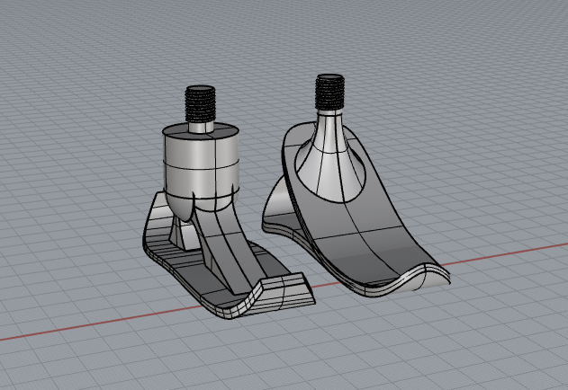
Precision-Control Foot Detail
Left: Rear Side View, Multi-directional rotating joint; Right: Front Side View, Data signal wiring encasement and curved 1/4" carbon fiber
Left: Rear Side View, Multi-directional rotating joint; Right: Front Side View, Data signal wiring encasement and curved 1/4" carbon fiber
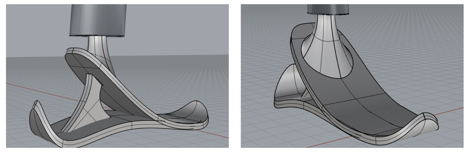
Ambulatory Foot Detail
Left: Rear Side View, Doubled 1/4” carbon fiber and high-energy absorbing support;
Right: Front View, Curved surface to deflect irregularities in ground surface
Left: Rear Side View, Doubled 1/4” carbon fiber and high-energy absorbing support;
Right: Front View, Curved surface to deflect irregularities in ground surface
The running leg (below) that I designed has a fairly similar design to typical running prostheses that currently exist. I decided to use a J-shaped 3.5" wide x .5" thick carbon fiber blade–the optimal design. It absorbs energy and exerts it outwards to add spring to each step. It has a shoe sole-like tread on the bottom of the blade to provide traction to the user. The blade is bottom-mounted to a stainless steel rod that is connected to the knee joint. This allows for not only a strong connection, but also a fluid one. It gives the user a great feel for the blade, something that doesn’t often happen with typical socket connection running prostheses.
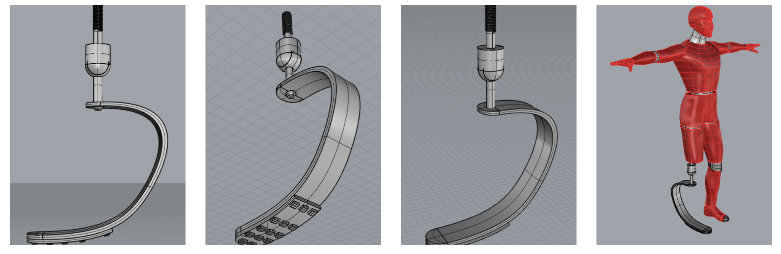
Far left: Side View, showing the 3.5” wide x .5” thick carbon fiber blade;
Center left: Base/Heel View, shows the gripping tread at base of blade;
Center right: Knee Joint View of bottom-mounted, multi-directional knee joint;
Far right: Full Body View
Center left: Base/Heel View, shows the gripping tread at base of blade;
Center right: Knee Joint View of bottom-mounted, multi-directional knee joint;
Far right: Full Body View